| Sign In | Join Free | My benadorassociates.com |
|
| Sign In | Join Free | My benadorassociates.com |
|
| Categories | Uniaxial Plastic Geogrid |
|---|---|
| Place of Origin: | China |
| Brand Name: | Hengquan |
| Certification: | ISO 9001 |
| Model Number: | TGDG35-300 KN |
| MOQ: | 1000m2 |
| Price: | Deliberation |
| Packaging Details: | packing belt |
| Delivery Time: | 5-8 days |
| Payment Terms: | L/C, T/T, Western Union |
| Supply Ability: | 40000M2 per week |
| Material: | PP or HDPE |
| width: | 3 meters |
| length: | 50 or 100 meters |
| color: | black |
| Tensile strength: | 35--300KN |
| Application: | Road Foundation Reinforcement |
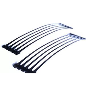
Road Foundation Reinforcement High Strength Polypropylene Uniaxial Plastic Geogrid
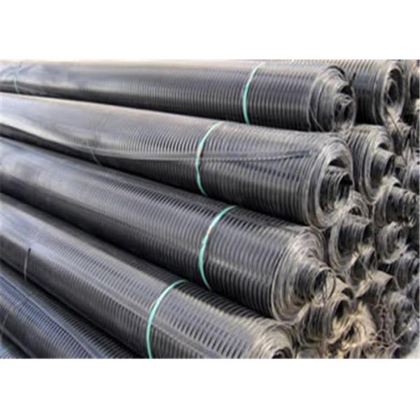
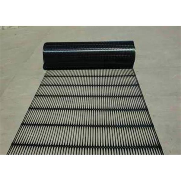
Uniaxial Plastic Geogrid Introduction
Plastic uniaxial geogrid is manufactured from plastic materials which may be high-density polypropylene or high-density polyethylene (HDPE) resins by the hot extruding process to make the resins into thin plates, the plates are punched into the regular holes for the formation of desired grids, and then the punching patterns are stretched longitudinally into the desired meshes to develop designed tensile strength.
Uniaxial Plastic Geogrid Specification
| Properties | GG60PP | GG80PP | GG110PP | GG150PP | GG260PP | GG300PP |
| Tensile Strength (kN/m) | 60 | 80 | 110 | 150 | 260 | 300 |
| Elongation Ratio | ≤10% | ≤10% | ≤10% | ≤10% | ≤10% | ≤10% |
| Strength at 2% Elongation (≥kN/m) | 17 | 26 | 32 | 45 | 94 | 105 |
| Strength at 5% Elongation (≥kN/m) | 35 | 48 | 64 | 90 | 185 | 195 |
| Roll Length (m) | 100 | 100 | 50 | 50 | 50 | 50 |
| Roll Width (m) | 1-3 | 1-3 | 1-3 | 1-3 | 1-3 | 1-3 |
Uniaxial Plastic Geogrid Feature
1,High tensile strength
2,Good sub-base reinforcement
3,Heavy duty foundation support
4,Anti-corrosion, erosion control
5,Good aperture stability
6,High junction efficiency
Uniaxial Plastic Geogrid Application
1. Uniaxial plastic geogrid for sale used to reinforce weak foundations.
2. Uniaxial plastic geogrid is used for reinforcing asphalt or cement pavement.
3. Uniaxial plastic geogrid is used to reinforce embankment slope and retaining wall.
4. Uniaxial plastic geogrid is used to reinforce river and sea embankments.
Key points of construction
Construction site: it is required to compact and level, and remove
the sharp protuberances.
Grid laying: on the flat and compacted site, the main stress
direction (longitudinal) of the grid installed and laid shall be
vertical to the axis of the embankment, and the laying shall be
flat without wrinkles, and shall be tensioned as far as possible.
The main stress direction of the laid grid is the full length
without joint. The connection between the width and width can be
bound and overlapped manually, and the lap width is not less than
10 cm. If the grid is more than two layers, the joints between
layers shall be staggered. After large area laying, the flatness
shall be adjusted as a whole. After filling a layer of soil and
before rolling, the grid should be tensioned again by manual or
machine tools, and the force should be uniform to make the grid in
the soil in a straight stress state.
Selection of filler: the filler shall be selected according to the
design requirements. It has been proved by practice that except
frozen soil, swamp soil, domestic garbage, chalk soil and
diatomite, they can be used as fillers. However, gravel soil and
sand soil have stable mechanical properties and little affected by
water content, so they should be preferred. The particle size of
filler shall not be greater than 15cm, and the grading of filler
shall be controlled to ensure the compaction weight.
Paving and compaction of filling materials: when the grid is laid
and positioned, it shall be filled and covered in time, and the
exposed time shall not exceed 48 hours. The flow operation method
of laying and backfilling can also be adopted. First pave the
filler at both ends, fix the grid, and then push forward to the
middle. The rolling sequence is from two sides to the middle.
During rolling, the roller can not directly contact with the
reinforcement material, and the vehicle is not allowed to drive on
it for fear of dislocation of reinforcement material. The
compaction degree of each layer is 20-30cm. The compactness must
meet the design requirements, which is also the key to the success
or failure of reinforced soil engineering.
Waterproof and drainage measures: in reinforced soil engineering,
the drainage treatment inside and outside the wall must be done
well; the foot protection should be done to prevent erosion; the
filtration and drainage measures should be set in the soil, and if
necessary, the geotextile and permeable pipe (or blind ditch)
should be set. Drainage shall be conducted in the way of dredging,
which shall not be blocked, otherwise hidden dangers will occur.
Construction technology editor
Firstly, the subgrade slope line shall be accurately set out. In
order to ensure the width of the subgrade, each side shall be
widened by 0.5m. After leveling the air dried foundation soil, 12t
vibratory roller, 25t tire roller or 2.5t rammer shall be used for
tamping, and the uneven place shall be leveled with manual
cooperation (no thin layer sticking and leveling).
After paving 0.3m thick medium (coarse) sand, manual and mechanical
leveling, 25t vibratory roller static pressure twice.
When laying the geogrid, the bottom surface of the geogrid should
be flat and dense. Generally, it should be paved and straightened
without curling or kinking. The two adjacent geogrids should be
overlapped by 0.2m. The overlapped part of the geogrid should be
connected with No.8 iron wire every 1 m along the subgrade
transverse direction, and fixed on the ground with U-shaped nails
every 1.5-2m.
After the first layer of geogrid is paved, the second layer of 0.2m
thick medium (coarse) sand shall be filled. The method is as
follows: the sand is transported to the construction site and
unloaded on one side of the subgrade, and then pushed forward by
bulldozer. After filling 0.1M within 2m on both sides of the
subgrade, the first layer of geogrid is turned up and then filled
with 0.1M medium (coarse) sand. Filling and pushing from both sides
to the middle is prohibited, and all kinds of machinery are
prohibited The geogrid with medium (coarse) sand filling can ensure
that the geogrid is flat without bulging and wrinkling. After the
second layer of medium (coarse) sand is leveled, horizontal
measurement shall be conducted to prevent uneven filling thickness.
After leveling, the 25t vibratory roller shall be used for static
pressing twice.
The construction method of the second layer of geogrid is the same
as that of the first layer. Finally, 0.3m medium (coarse) sand is
filled. The filling method is the same as that of the first layer.
After static pressing twice with 25t roller, the reinforcement of
subgrade base is completed.
After the third layer of medium (coarse) sand is rolled, two
geogrids are laid on both sides of the slope longitudinally along
the line, with an overlap of 0.16m, and connected by the same
method. Then, the earthwork construction is started, and the
geogrid is laid for slope protection. The laid sideline must be
measured for each layer, and the geogrid shall be buried in the
slope for 0.10m after slope repair.
When the slope geogrid is filled with two layers of soil, that is,
when the thickness is 0.8m, a layer of geogrid should be laid on
both sides at the same time, and so on until it is laid under the
soil on the road shoulder surface.
After the subgrade is filled, the side slope shall be repaired in
time, and the dry rubble protection shall be carried out at the
slope toe. In addition to 0.3m widening on each side of the
subgrade, 1.5% settlement shall be reserved.

|