0.96 Inch 128x64 Dots with SPI Interface OLED Graphic Module
0.96 Inch OLED Display Module Single Color SPI Interface
Product Specifications
| Product | 0.96 Inch OLED Display Module | Resolution | 128x64 Graphics |
|---|
| Driver IC | SSD1306BZ Or Equivalent | Outline Dimensions | 26.7x19.26x1.41 (mm) |
|---|
| Display Color | White&Blue Optional | Touch Screen | Without Touch Screen (Optional) |
|---|
| Viewing Direction | All Viewing Angles | Interface | 6800, 8080, SPI, I2C |
|---|
| Connection | Soldering/Hotbar (customizable) | Pin Number | 30 Pins (Can Be Customized) |
|---|
Product Drawing

Interface Pin Definition
| PIN NO. | SYMBOL | TYPE | FUNCTION DESCRIPTIONS |
|---|
| 1 | NC(GND) | P | It should be connected to external ground. |
| 2 | C2P | I | C1P/C1N-Pin for charge pump capacitor. C2P/C2N-Pin for charge pump
capacitor. Connect to each other with a capacitor. They must be
floated when the Charge pump not use. |
| 3 | C2N | | as above |
| 4 | C1P | | as above |
| 5 | C1N | | as above |
| 6 | VBAT | P | Power supply for charge pump regulator circuit. It must be
connected to external source when charge pump is used. It must be
float when charge pump is not used. |
| 7 | NC | | NC |
| 8 | VSS | P | Ground pin. It must be connected to external ground. |
| 9 | VDD | P | Power pin for logic circuit. It must be connected to external
source. |
| 10 | BS0 | | Interface Select Pins |
| 11 | BS1 | | Interface Select Pins |
| 12 | BS | | Interface Select Pins |
| 13 | CS# | I | Chip Select input pin. Active "L" |
| 14 | RES# | I | Hardware reset input pin. Active "L" |
| 15 | D/C# | I | This is Data/Command control pin. When the pin is pulled HIGH, the
data at D[7:0] is data. When the pin is pulled LOW, the data at
D[7:0] is command. In I2C mode, this pin acts as SA0 for slave
address section. When 3-wire serial interface is selected, this pin
must be connected to VSS |
| 16 | R/W# | I | read/write select pin. is selected, this pin must be connected to |
| 17 | E# | I | read/write enable pin. is selected, this pin must be connected to |
| 18 | D0 | I/O | These are 8-bit bi-directional data bus to be connected to
microprocessor's Data bus. When serial interface mode is selected,
D2 should be kept NC, D1 will be the serial data input: SDIN, D0
will be the serial clock input: SCLK. When I2C mode is selected,
D2, D1 should be tied together and serve as SDA and D0 is the
serial clock input, SCL. |
| 19-25 | D1~D7 | | These are 8-bit bi-directional data bus to be connected to
microprocessor's Data bus. When serial interface mode is selected,
D2 should be kept NC, D1 will be the serial data input: SDIN, D0
will be the serial clock input: SCLK. When I2C mode is selected,
D2, D1 should be tied together and serve as SDA and D0 is the
serial clock input, SCL. |
| 26 | IREF | I | Current reference for brightness adjustment. This is segment output
current reference pin. A resistor should be connected between this
pin and VSS .Set the current at 12.5 uA maximum. |
| 27 | VCOMH | O | COM signal deselected voltage level. A capacitor should be
connected between this pin and VSS. |
| 28 | VCC | P | Power supply for OLED driving voltage. A capacitor should be
connected between this pin and VSS, when charge pump is used. It
must be connected to external source when charge pump is not used. |
| 29 | VLSS | P | This is an analog ground pin. It should be connected to VSS
externally. |
| 30 | NC(GND) | P | It should be connected to external ground. |
This is a 0.96-inch, 128*64-pixel monochrome OLED graphic display
module, featuring a SPI communication interface. The core driver
chips are mostly SSD1306 (with some being SSD1315). It belongs to
passive OLED (PMOLED), with pixels self-luminous and no backlight
required. It has the characteristics of high contrast, wide viewing
angle, low power consumption, and fast response.
The physical size of the module is compact, with the display area
approximately 21.74*11.18mm. The overall module size is typically
around 26*26mm. The supply voltage ranges from 3.3V to 5.5V,
compatible with 3.3V and 5V systems. SPI is a 4-wire communication,
and some models can be switched to I2C through hardware. The
display color is mainly white, with blue and yellow-blue dual-color
options available. The operating temperature range is usually -40℃
to +85℃, suitable for industrial and consumer applications.
Core Features
- Self-luminous: Each pixel emits light independently. The black areas do not
consume power. The contrast is extremely high and the viewing angle
is close to 180°.
- Low power consumption: The standby current is extremely low. The current for full screen
illumination is only several tens of mA, making it suitable for
battery-powered devices.
- SPI interface: The communication speed is fast and the wiring is simple. It is
suitable for high-speed data refreshing and long-distance
connection.
- Mature driver: The SSD1306/SSD1315 drivers are complete, supporting mainstream
controllers such as Arduino, STM32, and ESP32, and there are
abundant open-source resources.
- Dual support for graphics and text: It can display characters, numbers, icons, simple graphics and
animations. The resolution meets the basic interaction display
requirements.
Main Applications
- Smart Wearables: Smart watches, bracelets, health monitors, showing time, heart
rate, steps, and exercise data.
- Internet of Things and Sensors: Local display terminals for temperature and humidity, air quality,
voltage and current sensors.
- Portable Medical Devices: Blood glucose meters, blood oxygen meters, electrocardiographs,
portable testers, showing measurement values and status.
- Industrial Control and Instruments: Small PLCs, frequency converters, thermostats, handheld testers,
status and parameter screens of auxiliary displays.
- Consumer Electronics and Hackers: Mini game consoles, desktop clocks, weather stations, Bluetooth
speakers, DIY electronic projects.
- Automotive Electronics: Vehicle small meters, tire pressure monitoring, auxiliary displays
of interior control modules.


Frequently Asked Questions
1. I want the LCD display 8 digits and the outline size is
65x30x2.8mm?
Answer: No problem. Firstly, please kindly send us your
specification/ drawing paper. If you have not the specification,
you can also provide your samples; we will recommend the suitable
one if it is standard products. Or we can customize for you based
on your own requirement.
2. This LCD is just what we want, but it is big size, do you have
any smaller size? And the display content need to be changed a
little.
Answer: For the segment type LCD module, if you need modify the
outline size or display content, a new LCD glass module is need. We
have to open new tooling for you.
3. This LCD display is HTN type, but I want STN type, can you make?
Answer: That's all right. We can change for you as per you request.
4. I want customize a new LCD module. Can you do?
Answer: Yes, we can. Please send your drawing paper. If you have
not, please advise me the outline size of the LCD display, display
information (Glass thickness, Polarizer, Display Type, Connector
mode, Storage Temp. Operating Temp. Supply Voltage, Viewing
direction, drive condition), we can customize for you.
5. What is leading time for tooling?
Answer: General speaking, it will cost 15 to 25 days after drawing
paper confirmation and tooling charge payment, we can report you
the exact time when you confirm the drawing paper.
6. Can you send us samples for checking?
Answer: Yes. Samples order is available.
7. What is the Leading Time?
Answer: If we have stock for the standard ones, the leading time is
one day after payment. If it is the mass production for special
ones, the leading time is about 15-30 days. suppose we can finish
earlier, we will report the information in advanced.
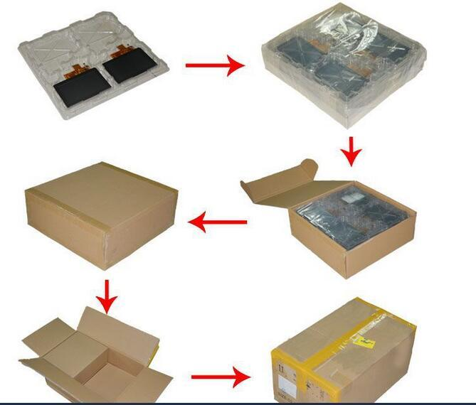
Packaging & Shipping
Packaging: Carton boxes, Cupboard, EPE, Blister Tray. About the package way,
it is up to the size of products, according to customer request and
demand. Different countries have not same requirement.
Shipping: Express way as DHL, Fedex, EMS, UPS, air shipping, sea shipping.
Any shipping method you prefer.

Payment Method